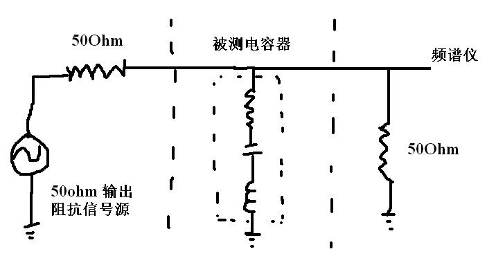
为了验证模型的准确性,我们可以使用信号发生器和频谱仪测量MLCC的插入损耗曲线。测试结果显示,使用TINA-TI v9可以很好的仿真MLCC安装到电路板上后的插入损耗特性,进而利用仿真结果指导电路设计,选择合适的滤波、旁路电容。
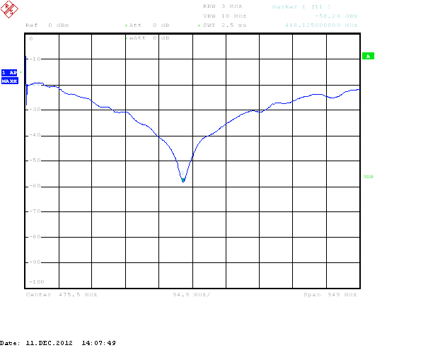
被测电容器 0603 56pF MLCC ,测得谐振频率点为 448.1Mhz,TINA仿真谐振频率点为450Mhz
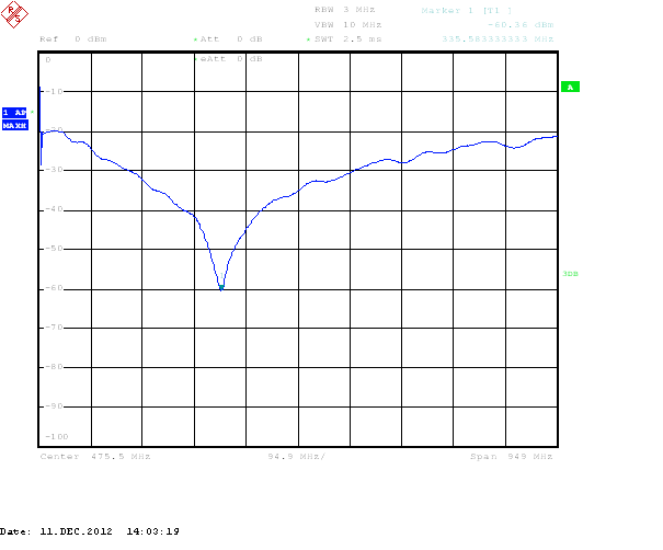
被测电容器 0603 100pF MLCC ,测得谐振频率点为 335.6Mhz,TINA仿真谐振频率点为338Mhz
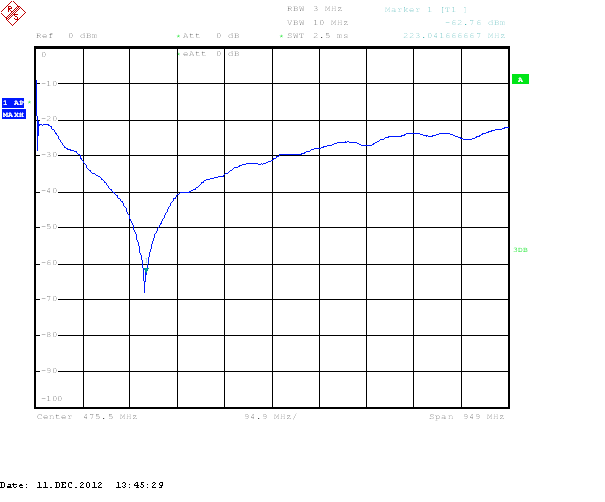
被测电容器 0603 220pF MLCC ,测得谐振频率点为 223.0Mhz,TINA仿真谐振频率点为230Mhz
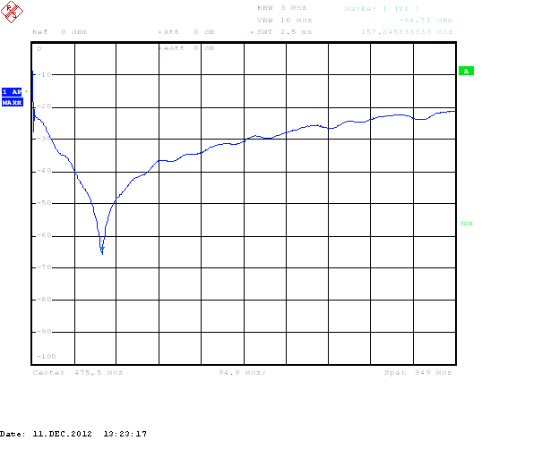
被测电容器 0603 470pF MLCC ,测得谐振频率点为 157.6Mhz,TINA仿真谐振频率点为156Mhz
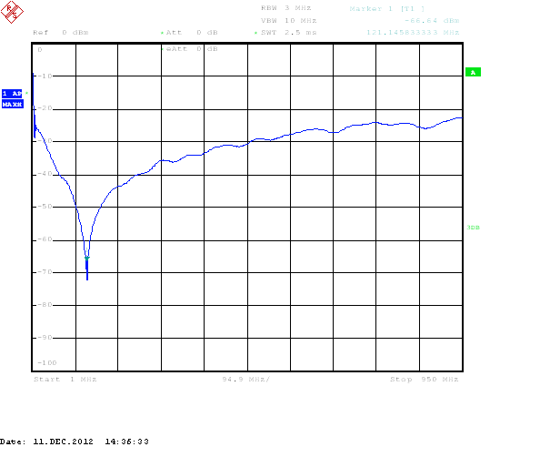
被测电容器 0603 820pF MLCC ,测得谐振频率点为 121.2Mhz,TINA仿真谐振频率点为118Mhz