If you have a related question, please click the "Ask a related question" button in the top right corner. The newly created question will be automatically linked to this question.
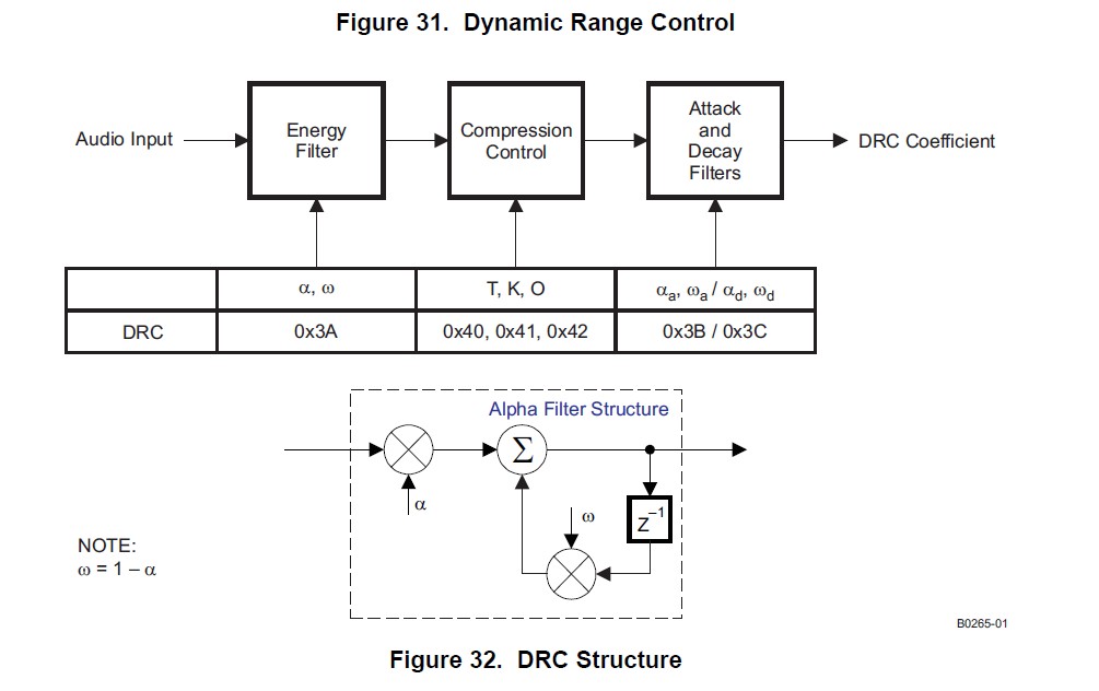
Energy Filter,Attack Filters ,Decay Filters的设定分别对应DRC中的系数“ae”,“aa”,"ad"。这些系数有的是9.23格式,有的是3.23格式。分别有相应的寄存器设置这些系数。例如TAS5711中的register0x3A-0x46。这些系数最终影响的是Energy time,Attack time,Decay time。这些系数通过固定的公式可以计算得到相应的时间。无论是codec还是TAS57XX系列,TI的GUI中都有工具,用户只需要在GUI上设定时间,GUI会通过I2C修改filter的寄存器控制这三个时间。用户开发时,只需要通过GUI导出寄存器,用MCU控制即可。所以,对于用户来说,这些filter系数都是中间变量,用户需要关心的是时间如何设定,对于DRC的影响。
对于这个时间,我暂且简单的解释一下:
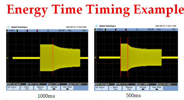
1.AAV estimator—This DRC element derives an estimate of the average absolute value (AAV) of the audio data stream into the DRC. A time constant, t_energy, is used to control the effective time window over which the AAV estimate is made.
2.Compression coefficient computation—This DRC element converts the output of the AAV estimator to a logarithmic number, determines the region where the input resides, and then computes and outputs the appropriate gain coefficient to the attack/decay element. Parameters K define the slopes of the gain curve for these three regions. T specify the boundaries of the regions, in terms of input level. O specify offsets of the gain curve relative to a 1:1 transfer function at the thresholds.
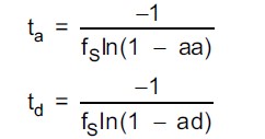
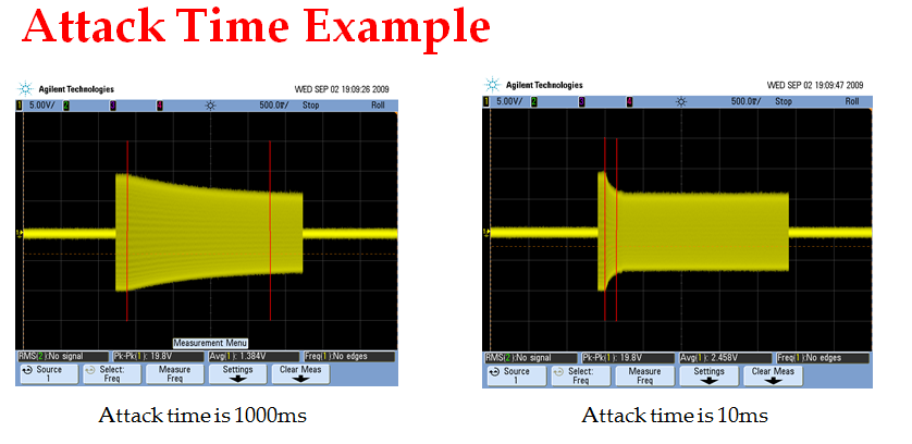
3.Attack/decay control—This DRC element controls the transition time of changes in the coefficient computed in the compression/expansion coefficient computation element. User-specified parameters t_a and t_d are used to set the attack and decay time constants used in the gain adjustment.
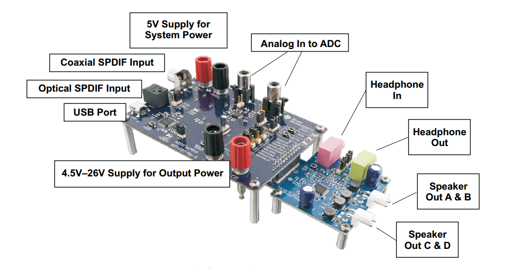
非常感谢Flora Wang ,也祝福你新年工作顺顺利利,步步高升,我之前的问题解决了,想在问下!TAS5717,有个耳机输入(HP-IN),耳机输出(HP-OUT),我选择HP-IN输入音源,
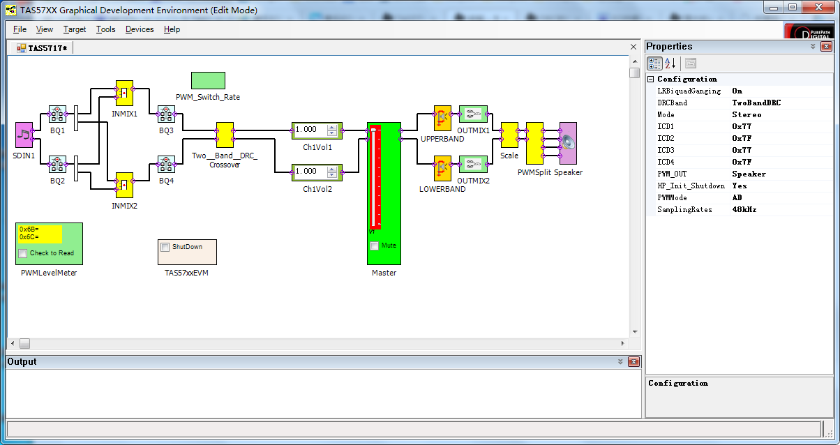
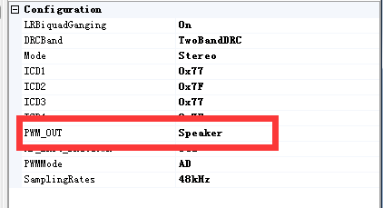
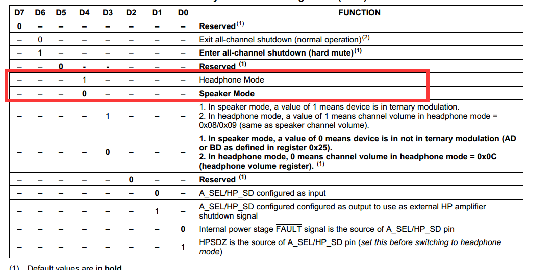
现在,我需要1.从Speak输出音乐 2.从HP-OUT输出音乐,这两者可以切换吗?在只有HP-IN当做音源输入的情况下,先不考虑I2S,只考虑模拟输入,我可以让音频从1.从Speak输出,或者从 2.从HP-OUT输出,这两者可以任意切换吗?目前我没有看到可以切换的方法,想知道,是否可以在这两者之间切换??非常感谢Flora Wang !
NOTE: The speaker and headphone cannot be used at the same time as they both share the same digital channel. DAP can be used for headphone volume 这点,耳机和扬声器无法公用!!!!