If you have a related question, please click the "Ask a related question" button in the top right corner. The newly created question will be automatically linked to this question.
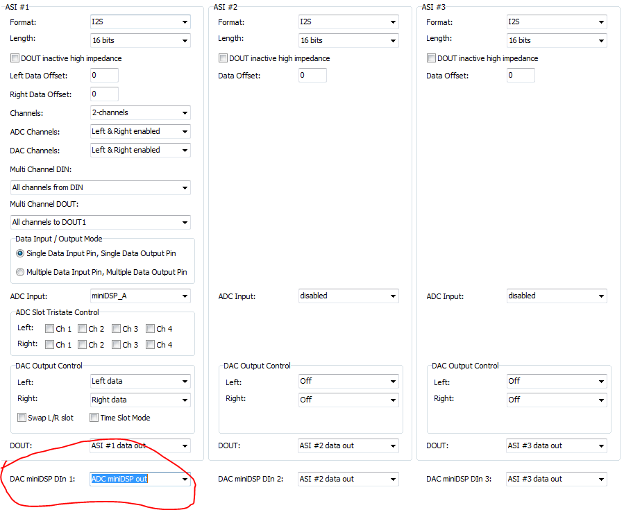
TLV320AIC3262 EVM 如何設置Line in 的聲音經由EQ調整後再輸出至LINE OUT及SPEAKER
################################################################ # ADC Stereo Record - High Performance # SE input signal from IN2L/IN2R # AVDDx_18, HVDD_18, CPVDD_18 = 1.8V; IOVDD, AVDD3_33, RECVDD_33 = 3.3V; SLVDD, SRVDD, SPK_V = 5V, DVdd = 1.8V # MCLK = 12.288, Fs = 48kHz # PLL Disabled, AOSR = 128, PTM_R1 # CM = 0.9V # Primary I2S Interface used with WCLK & BCLK as inputs to the device ################################################################
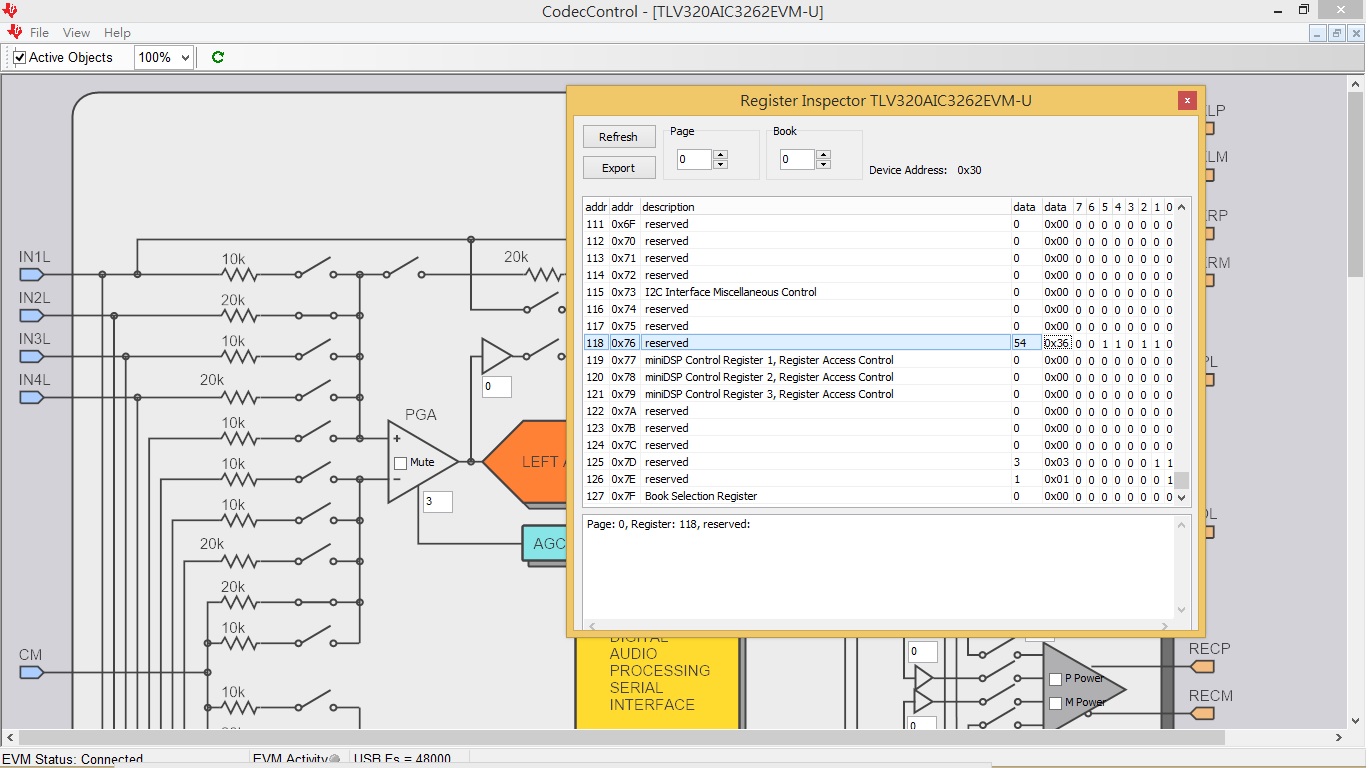
################################################################ # Software Reset ################################################################ w 30 00 00 # Initialize to Page 0 w 30 7f 00 # Initialize to Book 0 w 30 01 01 # Initialize the device through software reset d 1 # Delay 1 millisecond
################################################################ # Power and Analog Configuration ################################################################ w 30 00 01 # Select Page 1 w 30 01 00 # Disable weak AVDD to DVDD connection and make analog supplies available w 30 7a 01 # REF charging time = 40ms w 30 79 33 # Set the quick charge of input coupling cap for analog inputs
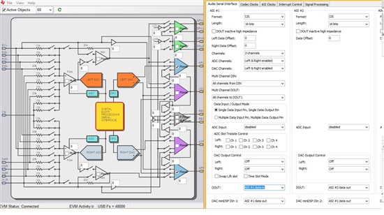
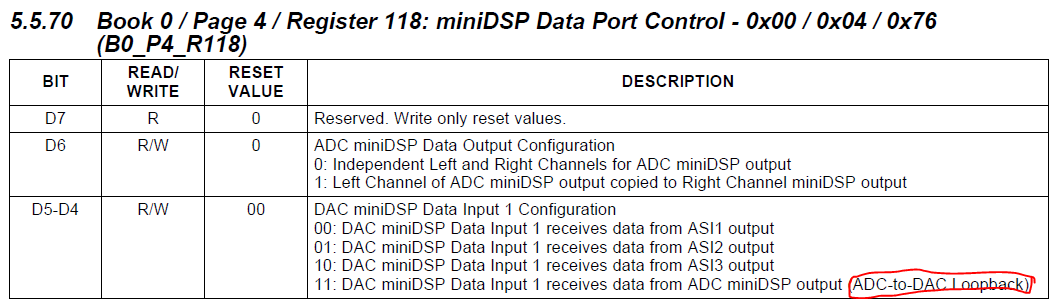
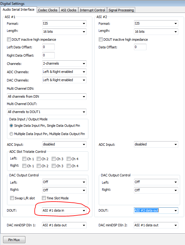
################################################################ # Audio Serial Interface Routing Configuration - Audio Serial Interface #1 # ASI #1 recording ################################################################ w 30 00 04 # Select Page 4 w 30 01 00 # Audio Serial Interface #1 is set to I2S mode, 16-bit w 30 0a 00 # Route ASI#1 WCLK and BCLK to WCLK1 pin and BCLK1 pin
################################################################ # Signal Processing Settings ################################################################ w 30 00 00 # Select Page 0 w 30 3d 02 # Set the ADC PRB Mode to PRB_R1
w 30 00 01 # Select Page 1 w 30 08 00 # Set the input common mode to 0.9V w 30 34 20 # Route IN2L and CM1 to LEFT ADCPGA with 20K input impedance w 30 36 80 w 30 37 20 # Route IN2R and CM1 to RIGHT ADCPGA with 20K input impedance w 30 39 80 w 30 3B 06 # Left Channel Analog ADC PGA = 3 dB, Results in Overall Channel Gain of 0dB w 30 3C 06 # Right Channel Analog ADC PGA = 3 dB, Results in Overall Channel Gain of 0dB w 30 3D 00 # ADC Analog programmed for PTM_R4
w 30 00 00 # Select Page 0 w 30 51 C0 # Power-up ADC Channel w 30 52 00 # Unmute ADC channel and Fine Gain = 0dB
######################################### # Signal processing ######################################### # # select page 0 w 30 00 00 # # set DAC PRB mode to PRB_P1 w 30 3C 01 # ################################
####################################################### # DAC configuration ####################################################### # # select page 1 w 30 00 01 # # Set DAC PTM mode to PTM_P3 w 30 03 00 w 30 04 00 #
# Route LDAC to HPL and route RDAC to HPR, don't power up HP driver yet w 30 1B 30 # # select page 0 w 30 00 00 # # power up LDAC and RDAC w 30 3F C0
# # select page 0 w 30 00 00 # # power up LDAC and RDAC w 30 3F C0 # # select page 1 w 30 00 01 # # set Headphone in Ground-centered Mode, HPL is still muted w 30 1F B9 # # HPR has the same gain as HPL, HPR is still muted w 30 20 B9
# # Charge pump runs of Oscillator clock with divider = 4 w 30 21 28 # # headphone output offset correction (default setting) w 30 22 3E
# Charge pump to power up on the headphone power up in Ground-centered Mode w 30 23 30
# # unmute HPL driver, set gain = 0 dB w 30 1F 80 # # unmute HPR driver, set gain = 0 dB w 30 20 80 # # select page 0 w 30 00 00 # # Unmute LDAC and RDAC digital volume w 30 40 40 # # select page 1 w 30 00 01 # reduce HP power to 25 percent w 30 09 70 # # power up HPL/HPR w 30 1B 33 # ##################################################
# select page 1 w 30 00 01 # increase HP power to 100 percent w 30 09 10


