采用STM32和ADS1298开发12导心电测量仪。ADS1298配置为continuous模式已经工作正常,现在要改为single-shot模式。在single-shot模式下,能正确读取芯片ID,也能正确判断导联是否脱落,但ADC的数据明显不正确。主要代码如下:
1、ADS1298寄存器配置
uint8_t RegisterData[25] = {0xC2, //0x82, 0x03, /* CONFIG1 */ //8kSPS
0x10, /* CONFIG2 */ //RLD
0xDC,/*0xD4*/ /* CONFIG3 */
0x07/*0x0F*/, /* LOFF *///
0x00, 0x00, 0x00, 0x00, 0x00, 0x00, 0x00, 0x00,/*CHnSET*/
0xFF, /* RLD_SENSP *///
0xFF, /* RLD_SENSN *///
0xFF, /* LOFF_SENSP *///所有通道的正端均进行脱落检测
0xFF, /* LOFF_SENSN *///所有通道的负端均进行脱落检测
0x00, /* LOFF_FLIP */
0, /* LOFF_STATP,导联正端连接状态,只读,不需要设*/
0, /* LOFF_STATN,导联负端连接状态,只读,不需要设*/
0, /* GPIO */
0, /* PACE */
0xF0, /* RESP */
0x2E,//0x2A/*0x22*/, /* CONFIG4 */ //采用0x2A或0x2E为单次模式,采用0x22为连续AD模式
0x0B, /* WCT1 *///WCT配置管脚
0xE2 /* WCT2 */
};
2、ADS1298初始化部分程序
void ADS1298_Init( void )
{
    uint8_t device_id = 0;
    ADS1298_IO_Init();//硬件端口初始化
    ADS1298_PIN_CS = LOW;
    ADS1298_RESET();
    device_id = ADS1298_GetID();

    if( device_id == 0x92 ) //ID正确
    {
        ADS1298_WriteMultiReg( ADS1298_CONFIG1_REG, RegisterData, 25 ); //配置ADS1298
    }
    else
    {
    }

}
3、读取数据子程序
void ADS1298_ReadDataOneShot() //  use in Stop Read Continuous mode when DRDY goes low
{
    uint8_t inByte, inByte1, inByte2, inByte3;
    int i;
    uint32_t stat_1 = 0;

    for( i = 0; i < 8; i++ )
    {
        ADSChannelData[i] = 0;
    }

    ADS1298_WriteCmd( ADS1298_CMD_RDATA );

    // READ CHANNEL DATA FROM FIRST ADS IN DAISY LINE
    for( i = 0; i < 3; i++ ) 			//  read 3 byte status register (1100+LOFF_STATP+LOFF_STATN+GPIO[7:4])
    {
        inByte = ADS1298_ReadByte( );
        stat_1 = ( stat_1 << 8 ) | inByte;
    }

    /*输出电极脱落状态*/
    for( i = 0; i < 16; i++ )
    {
        uint8_t tmp = 0;
        tmp = ( stat_1 >> ( 19 - i ) ) & 0x01;

        if( tmp == 0x01 ) //导联脱落检测正常
        {
            if( i <= 7 )
            {
                printf( "第%d路正端脱落\r\n", 8 - i );
            }
            else
            {
                printf( "第%d路负端脱落\r\n", 16 - i );
            }
        }
    }

    for( i = 0; i < 8; i++ )
    {
        inByte1 = ADS1298_ReadByte( );
        inByte2 = ADS1298_ReadByte( );
        inByte3 = ADS1298_ReadByte( );
        ADSChannelData[i] = ( inByte1 << 16 ) | ( inByte2 << 8 ) | inByte3;
    }

    printf( "%d\r\n", ADSChannelData[0] ); //数据输出不正常
}
4.主函数
int main( void )
{
    NVIC_PriorityGroupConfig( NVIC_PriorityGroup_2 ); //设置系统中断优先级分组2
    delay_init( 168 );   //初始化延时函数
	  uart_init(115200);
    ADS1298_Init();//

    /*--1--测试读ID号和寄存器,测试通过*/
//    while( 1 )
//    {
//        uint8_t IDtmp = 0;
//        IDtmp = ADS1298_GetID();//正确应该是0x92
//        IDtmp = IDtmp;
//        delay_ms( 500 );
//        ADS1298_WriteReg( 0x10, 0xff );
//        delay_ms( 500 );
//        IDtmp = ADS1298_ReadReg( 0x10 ); //应该是前面写的0xff
//        IDtmp = IDtmp;
//    }
		ADS1298_WriteCmd(ADS1298_CMD_SDATAC);

		while( 1 )
    {
			uint32_t tmp = 0;
			ADS1298_WriteCmd(ADS1298_CMD_START);

			while(ADS1298_IsReady()!=1);

			ADS1298_ReadDataOneShot();

			delay_ms(10);

			tmp = ADSChannelData[0];
			tmp = ADSChannelData[1];
			tmp = ADSChannelData[2];
			tmp = ADSChannelData[3];
			tmp = ADSChannelData[4];
			tmp = ADSChannelData[5];
			tmp = ADSChannelData[6];
			tmp = ADSChannelData[7];

		}
}
5、判断是否转换结束函数,主函数中调用
uint8_t ADS1298_IsReady( void )
{
    return ( ADS1298_PIN_DRDY == 0 );
}
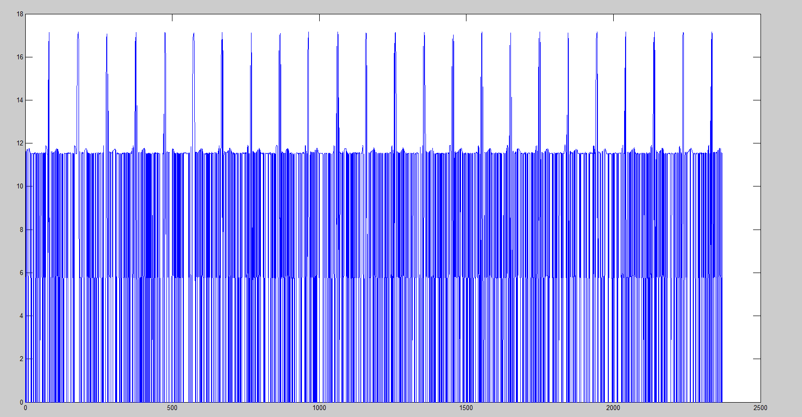
现在无论是否加心电信号源,通过printf函数串口输出的数据基本都是如下:
8388607
0
8388607
8388607
8388607
0
8388607
0
0
0
8388607
8388607
0
8388607
0
8388607
8388607
8388607
0
8388607
0
0
0
8388607
8388607
求助~