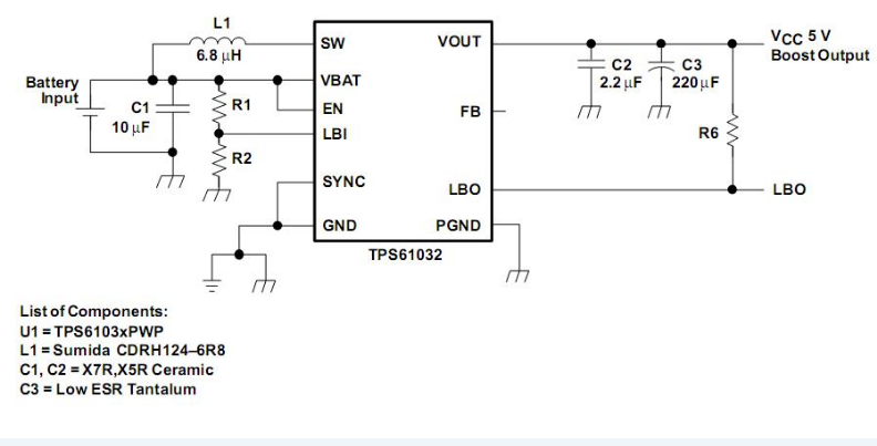
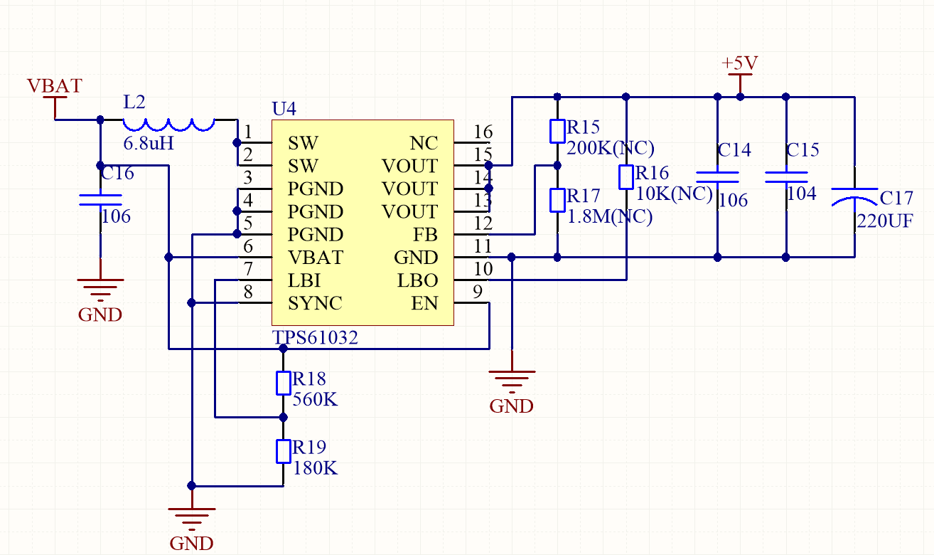
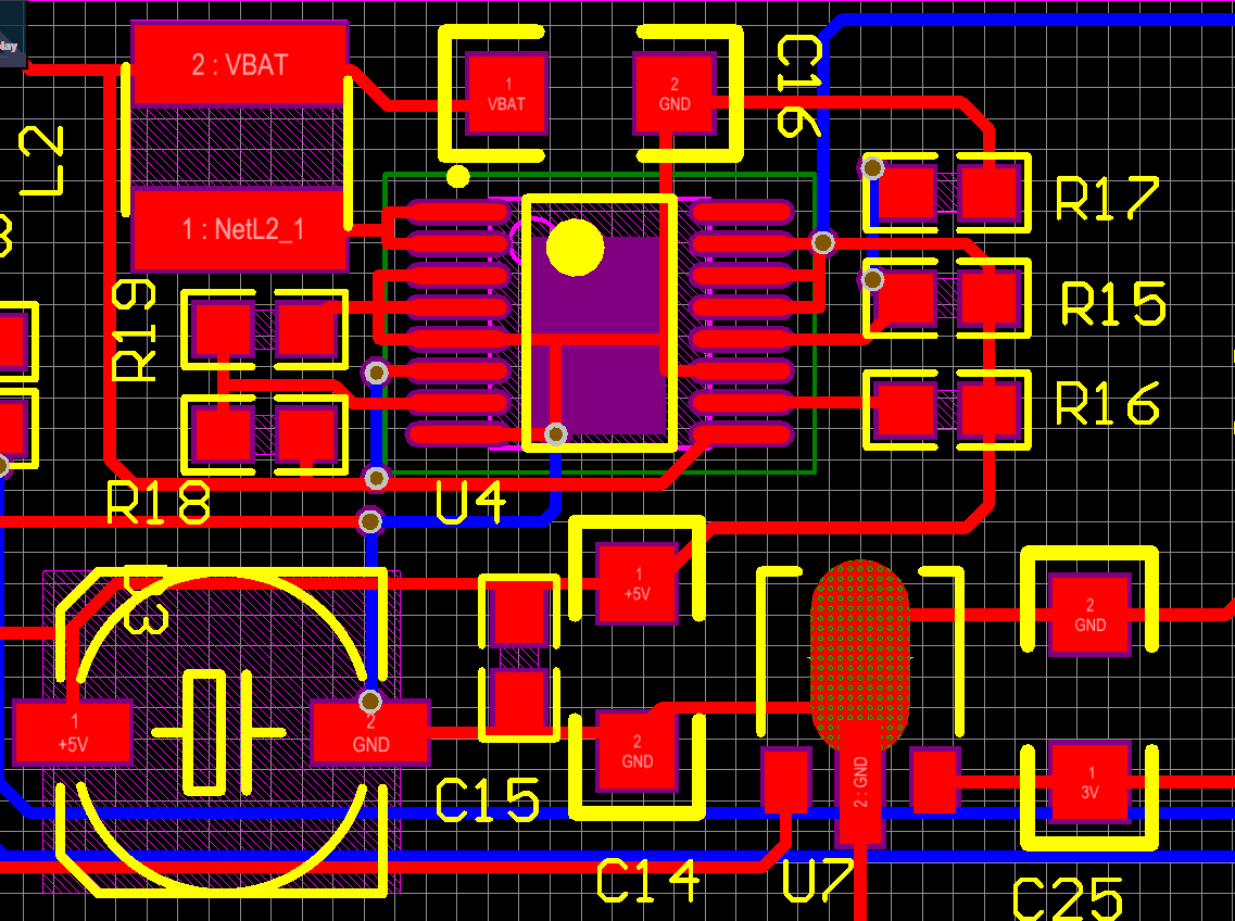
This thread has been locked.

If you have a related question, please click the "Ask a related question" button in the top right corner. The newly created question will be automatically linked to this question.

TPS61032按照典型电路无法工作

Other Parts Discussed in Thread: TPS61032

使用TI官网PDF绘制原理图如下图:

PCB布板如下图:

出现的现象如下:

1、使用直流电源接入2.5V,限流500mA,直接进入CC模式,输入电压降到1.1V,电流0.5A,系统无输出;

2、测试输入端VBAT+与GND电阻只有2R左右;

3、拆除电感后接入电源2.5V,CV模式,电流几乎0,但还是无输出电压,测试输入端VBAT+与GND电阻1M+。

疑问:

1、为什么电感接入之后输入端的电阻如同短路;

2、如何排查该问题,焊接两个板子均一致的现象;

3、设计过程需要特别注意什么。

望给以答疑,不胜感激!