If you have a related question, please click the "Ask a related question" button in the top right corner. The newly created question will be automatically linked to this question.
When MODE pin voltage is greater than 1.2 V, diode emulation mode threshold, forced PWM mode is enabled, allowing current to flow in either direction through the high-side Nchannel MOSFET switch. When MODE pin voltage is less than 1.2 V, the controller works in diode emulation mode. Skip cycle comparator is activated as a default condition when the MODE pin is left floating. If the MODE pin is grounded, the controller still operates in diode emulation mode, but the skip cycle comparator will not be triggered in normal operation, this enables pulse skipping operation at light load
你可以直接将MODE接到GND. 不需要上拉到VCC和接对GND电阻。
The LM5121 switching frequency is programmable by a single external resistor connected between the RT pin and the AGND pin. The resistor should be located very close to the device and connected directly to the RT and AGND pin. To set a desired switching frequency (fSW), the resistor value can be calculated from Equation 4.


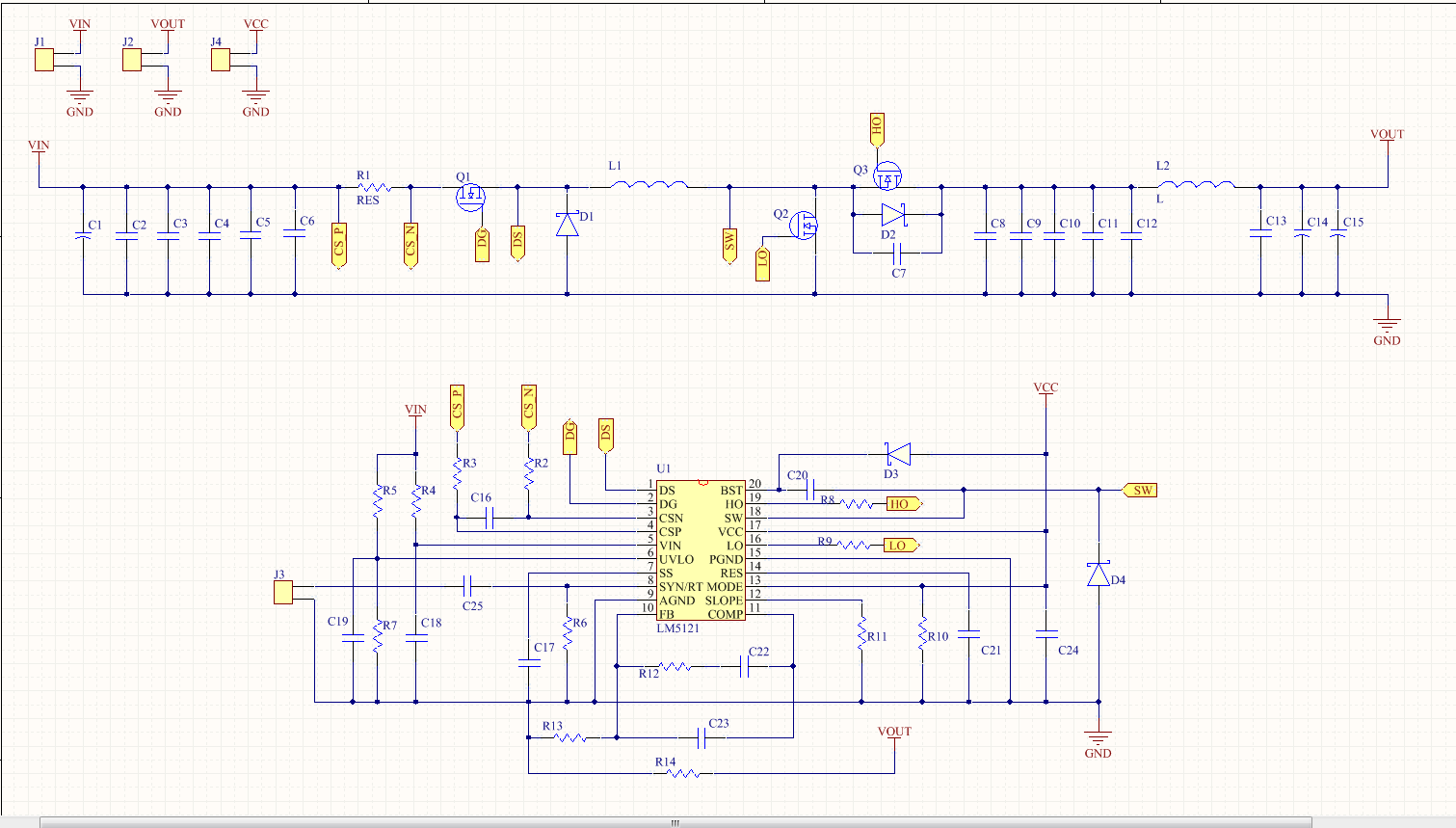 如图所示,要使电路工作在连续模式,Fsw约为100KHz,R10和R6应该怎样取值,有相应的计算公式吗?