一、母线电压采集问题:文件目录(C:\ti\controlSUITE\development_kits\TMDSIDDK_v2.0\IDDK_PM_Servo_F2837x_v2_00_00_00)
目录下的IDDK_PM_Servo_F2837x.C文件中:
1、母线电压采样配置:
// Bus Voltage Feedback at B0 (not used) 母线电压反馈
// **************************************
AdcbRegs.ADCSOC3CTL.bit.CHSEL = 0; // SOC3 will convert pin B0
AdcbRegs.ADCSOC3CTL.bit.ACQPS = 30; // sample window in SYSCLK cycles
AdcbRegs.ADCSOC3CTL.bit.TRIGSEL = 5; // trigger on ePWM1 SOCA/C
//源程序没有以下这两句,添加后进行仿真,旋转母线电压20V~30V,使用示波器观察MCU端口有电压变化,而软件读取ADCbResultRegs.ADCPPB4RESULT 中的数据始随电压值变化,通过读取的寄存器或保存数组中可以看到,存在一两个数据是错误的,不知道问题出在哪里,其它值根据测得电压值计算是对的。
AdcbRegs.ADCPPB4CONFIG.bit.CONFIG = 3; //dx PPB is associated with SOC3
AdcbRegs.ADCPPB4OFFCAL.bit.OFFCAL = 0; //dx Write zero to this for now till offset ISR is run
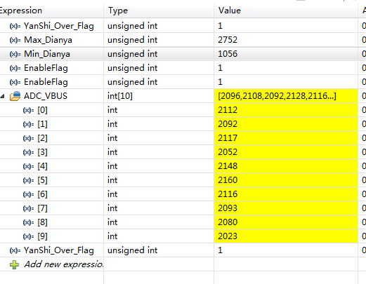
以下是仿真时,读取寄存器值、读取多个电压值、电压最大值、最小值截取,如下图:
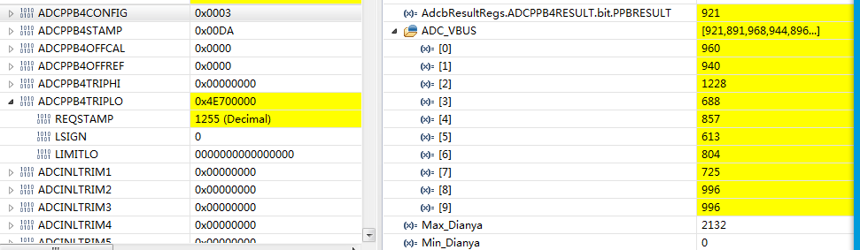
以上电压值是通过ADC_VBUS[20] = AdcbResultRegs.ADCPPB4RESULT.bit.PPBRESULT;得到的,会仿真时也会发现寄存器中的值出错,该图中1228值就是错误的;通过软件进行筛选最大最小值后,最大值2132,最小值会更新到0;问题找出。
2、电流采样部分配置:
#if (CGND == HOT)
// Shunt Motor Currents (SV) @ A4 反馈电流Ifb-SV
// ********************************
AdcaRegs.ADCSOC0CTL.bit.CHSEL = 4; // SOC0 will convert pin A4 采样电流管脚A4 (A4 反馈电流Ifb-SV)
AdcaRegs.ADCSOC0CTL.bit.ACQPS = 30; // sample window in SYSCLK cycles 采样窗口设置
AdcaRegs.ADCSOC0CTL.bit.TRIGSEL = 5; // trigger on ePWM1 SOCA/C 根据根据需要进行配置
// Configure the post processing block (PPB) to eliminate subtraction related calculation
AdcaRegs.ADCPPB1CONFIG.bit.CONFIG = 0; // PPB is associated with SOC0
AdcaRegs.ADCPPB1OFFCAL.bit.OFFCAL = 0; // Write zero to this for now till offset ISR is run
// Shunt Motor Currents (SW) @ B4 反馈电流Ifb-SW
// ********************************
AdcbRegs.ADCSOC0CTL.bit.CHSEL = 4; // SOC0 will convert pin B4 采样电流管脚B4
AdcbRegs.ADCSOC0CTL.bit.ACQPS = 30; // sample window in SYSCLK cycles 在系统时钟周期采样窗口
AdcbRegs.ADCSOC0CTL.bit.TRIGSEL = 5; // trigger on ePWM1 SOCA/C 触发源选择
// Configure PPB to eliminate subtraction related calculation
AdcbRegs.ADCPPB1CONFIG.bit.CONFIG = 0; // PPB is associated with SOC0
AdcbRegs.ADCPPB1OFFCAL.bit.OFFCAL = 0; // Write zero to this for now till offset ISR is run
#endif
电压采样部分我对照一下手册,没有找出问题在哪里,又对照一下电阻采样部分配置,认为配置方式是一样的,而电流采样部分确是正确的(电机可以正常运行,电流波形可以看到);所有目前没有搞明白问题所在,麻烦你帮忙解决一下,多谢!