This thread has been locked.

If you have a related question, please click the "Ask a related question" button in the top right corner. The newly created question will be automatically linked to this question.

串入电容是为了高速信号阻抗匹配吗?tms320f28377d/CDCLVC1102PW/AMC1306

TI工程师:

          您好!最近看了《Three-Phase High PWM Frequency GaN Inverter Reference Design TIDA-00915》参考设计。对里面的高速电路有一些细节不理解,请指点。

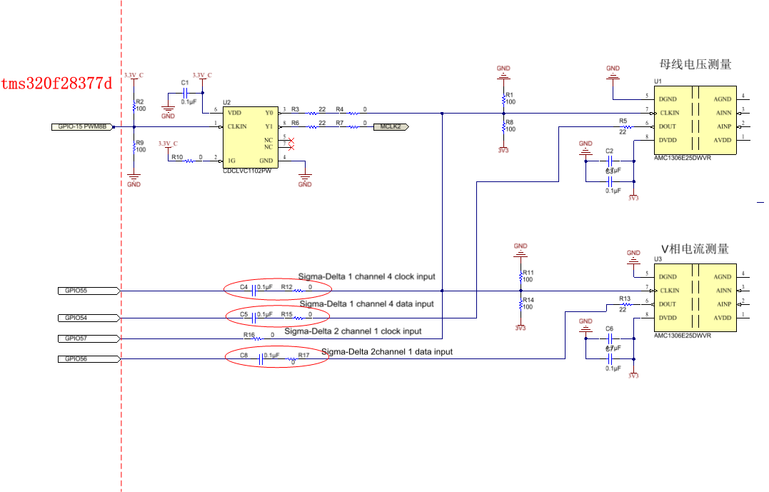
          电路信号链路如下图所示。tms320f28377d的PWM作为时钟信号通过 buffer(CDCLVC1102PW)为4片Sigma-Delta ADC转换器(图中只画了2片)提供时钟信号。设计者考虑阻抗匹配,并联两个100欧姆和串联22欧姆电阻实现阻抗匹配。但为什么会串入0.1uF的电容呢?

具体问题如下:

   1、将Sigma-Delta ADC输出信号串入0.1uF电容,再进入DSP管脚,是阻抗匹配的需要吗?串入容值的大小计算,您能推荐文档吗?

   2、设计者也不是所有都串入了0.1uF电容,直流母线电压测量的clk,就没有串入。是漏掉了,还是其它原因呢?

   3、设计者多处串入0欧姆电阻,是调试需要,(因为28377的Sigma-Delta ADC模式2 可以不需要时钟信号),还是有其它讲究?

   4、关于何时需要考虑阻抗匹配?一些文档说,对于20MHz信号,PCB走线超过50mm,就需要考虑。另一文献说信号上升沿和下降沿小于6倍信号延时就需要考虑。您对何时需要考虑,有什么建议吗?因为TI参考电路《使用 SAR 和 Σ-Δ ADC 在保护继电器中实现集成诊断功能的参考设计 TIDA-00810》同样的电路,就没有考虑阻抗匹配。

TIDA-00915-C-E1(001)_Sch.PDF
  • 1.是DSP输出串了电容吧     这个说明下级有AC耦合的要求

    2.DSP输入引脚肯定不能串电容    记得MCU中没有AC耦合后输入的功能

    3.0欧姆电阻一般都是为了调试或功能切换使用的  

    4.阻抗匹配主要在layout设计时考虑的  这个由板材  叠层  板厚等各种因素决定

  • 感谢您的回复。因为SD模块而言,两个输入clk和DATA。所以都是DSP输入引脚。为什么需要串入电容,这也是我疑惑的地方。毕竟系统通过了测试,应该这么做是可行的。

  • Hello ,

    looks like this a modified schematic from the Altium design files. Please see the variants information in Altium, which show that some resistors are DNP.

    (1) I had the 0.1uF capacitor on the data signal, it does not have an effect in the impedance matching of the data signal. The 0.1uF capacitor would be low impedance to the 20Mhz data signal. This was kept for testing. Please remove this capacitor and replace with a short. Thanks, I will add a note in design guide to make it clear. 

    (2) Some resistors are for debugging.

    R12 and R16 on clock lines are DNP when using the Manchester encoded version of AMC1306 as there is no need to give the clock back to C2000 when data is Manchester encoded.

    R4, R7, R15 and R17 are used for debugging either open or short according to the need. This can be eliminated.

    R5, R13, R3,R6 are for impedance matching (series termination). 

    Also,  R1 and  R8, or  R11 and R14 are placed for parallel termination, this should not be placed when using series termination. After testing i have seen that series termination works best.

    (3) I had long distance and also a cable between AMC1306 and C2000 about 10cm. The issues due to propagation delay is eliminated by using Manchester encoded data. However impedance matching is required for signal integrity. Example: one of the problems I have seen with out impedance matching is excessive ringing at the signal edges. I have done only a rough impedance matching using the resistors, but I have not done the impedance control in the PCB manufacturing. At 20Mhz one may not see a problem depending on the board and cable, I would still put it as provision.

    also note, CDCLVC1102 has a internal series termination resistance for 50Ohm. You may need to add to this.

    (4) TIDA-00915-C does have provision for 4 clock input to the C2000, but since I am using the Manchester version of the AMC1306, I have DNP resistors on these clock lines. effectively I have only 4 AMC1306, being driven. This works very well for TIDA-00915, unfortunately, I do not have any info on the max number of AMC1306. Please do post on the Clock and Timing Forum about max number of loads for CDCLVC1102.

    Regards

    Nelson