我用28335做伺服电机控制,上电后先读一下U相电流,V相电流对应的AD口的零漂(连续采样1024次然后求平均),然后在电机正式运行起来后用采样的值减去零漂。业内也都是这种处理方法。但最近遇到个奇怪的问题:
我两块板子,芯片也是同一批的,烧录同一个程序,硬件一模一样,一台运行正常,另一台会频繁报警,仔细查找后判断ADC可能有问题,发现不正常的这一台测到的ADC结果异常,已经不是精度问题了(正常情况下零漂也就是10~20个LSB,但不正常的这一台测到的是1000多!)
然后修改ADC初始化部分的代码:发现有一句的改动对这我的ADC测到的值影响很大
EALLOW;
SysCtrlRegs.PCLKCR0.bit.ADCENCLK = 1;
ADC_cal();
EDIS;
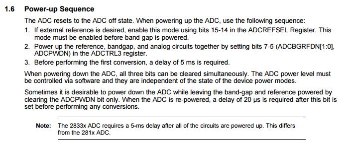
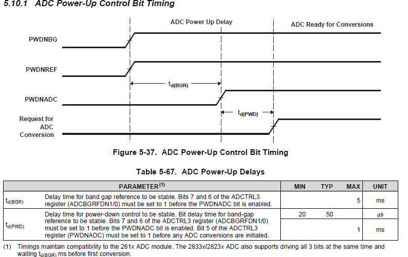
// To powerup the ADC the ADCENCLK bit should be set first to enable
// clocks, followed by powering up the bandgap and reference circuitry.
// After a 5ms delay the rest of the ADC can be powered up. After ADC
// powerup, another 20us delay is required before performing the first
// ADC conversion. Please note that for the delay function below to
// operate correctly the CPU_CLOCK_SPEED define statement in the
// DSP28_Examples.h file must contain the correct CPU clock period in
// nanoseconds. For example:
AdcRegs.ADCTRL3.all = 0x30;
AdcRegs.ADCTRL3.bit.ADCBGRFDN = 0x3; // Power up bandgap/reference circuitry
DELAY_US(ADC_usDELAY); // Delay before powering up rest of ADC
AdcRegs.ADCTRL3.bit.ADCPWDN = 1; // Power up rest of ADC
DELAY_US(ADC_usDELAY2); // Delay after powering up ADC
最初我用的是绿色部分的代码初始化给ADC内部电路上电,当我参照黄色部分的注释改成红色部分的程序时,板子异常的情况好很多。而且当我把里面的延时加到ms级的时候问题就不会出现了。
我想问一下这个两句话的区别是什么呢?延时的长短带来的不同后果是什么?而且我发现不同版本28335adc初始化例程,两种方式都用过。。。。。
而且数据手册说如果用外部参考时候,需要先配置外部参考再上电,感觉好奇怪。。。。