This thread has been locked.
If you have a related question, please click the "Ask a related question" button in the top right corner. The newly created question will be automatically linked to this question.
专家好!
以前用MSP430F4152的ADC测试电池电压很简单,只需要开通对应通道,内部有一个二分之一的分压,开通内部参考基准电压源即可测试,但现在使用FR4133却没有这个通道,请问专家怎么实现测试电池电压(DVCC)?谢谢!
可以用外部电阻分压,然后用一路adc采样
wenxiang xu 说: 专家好! 以前用MSP430F4152的ADC测试电�电压很简单,只需要开通对应通道,内部有一个二分之一的分压,开通内部参考基准电压源即可测试,但现在使用FR4133却没有这个通道,请问专家怎么实现测试电池电压(DVCC)?谢谢!
以前用MSP430F4152的ADC测试电�电压很简单,只需要开通对应通道,内部有一个二分之一的分压,开通内部参考基准电压源即可测试,但现在使用FR4133却没有这个通道,请问专家怎么实现测试电池电压(DVCC)?谢谢!
有一个很简单的办法,用DVCC 做ADC的参考电压,去采 内部基准的电压。然后反推出DVCC的电压。
//******************************************************************************
//  MSP430FR413x Demo - ADC, Lo_Batt, Set P1.0 if AVcc < 2.50V
//
//  Description: A single sample is made on A13 (Vref) with reference set to
//  DVCC. Software sets ADC10SC to start sample and conversion
//  - ADC10SC automatically cleared at EOC. Once conversion is completed, the
//  following equation is used to calculate DVCC = (1023 * 1.5) / adcResult.
//  if DVCC is < 2.5V, P1.0 set indicating a lo_Batt condition, else reset.
//
//                MSP430FR4133
//             -----------------
//         /|\|              XIN|-
//          | |                 |
//          --|RST          XOUT|-
//            |                 |
//            |A13 (Vref)   P1.0|-->LED
//
//  William Goh
//  Texas Instruments Inc.
//  August 2014
//  Built with IAR Embedded Workbench v5.60 & Code Composer Studio v6.0
//******************************************************************************
#include <msp430.h>

unsigned int adcResult;                     // Temporarily stores the ADC value
                                            // that was read from ADCMEM0
int main(void)
{
    volatile unsigned long dvccValue;       // Calculated DVCC value

    WDTCTL = WDTPW | WDTHOLD;               // Stop WDT

    P1DIR |= BIT0;                          // Set P1.0 to output direction

    // Disable the GPIO power-on default high-impedance mode to activate
    // previously configured port settings
    PM5CTL0 &= ~LOCKLPM5;

    // Configure ADC10
    ADCCTL0 &= ~ADCENC;                     // Disable ADC
    ADCCTL0 = ADCSHT_2 | ADCON;             // ADCON, S&H=16 ADC clks
    ADCCTL1 = ADCSHP;                       // ADCCLK = MODOSC; sampling timer
    ADCCTL2 = ADCRES;                       // 10-bit conversion results
    ADCIE = ADCIE0;                         // Enable ADC conv complete interrupt
    ADCMCTL0 = ADCINCH_13 | ADCSREF_0;      // A13 ADC input select = 1.5V Ref
                                            // Vref = DVCC
    // Configure reference module located in the PMM
    PMMCTL0_H = PMMPW_H;                    // Unlock the PMM registers
    PMMCTL2 |= INTREFEN;                    // Enable internal reference
    while(!(PMMCTL2 & REFGENRDY));          // Poll till internal reference settles

    while(1)
    {
        ADCCTL0 |= ADCENC | ADCSC;          // Sampling and conversion start
        __bis_SR_register(LPM0_bits | GIE); // Enter LPM0, ADC_ISR will force exit
        __no_operation();                   // For debug only

        // To calculate DVCC, the following equation is used
        // DVCC = (1023 * 1.5) / adcResult
        // The following equation is modified to use only integers instead
        // of using float. All results needs to be divided by 100 to obtain
        // the final value.
        // DVCC = (1023 * 150) / adcResult
        dvccValue = ((unsigned long)1023 * (unsigned long)150) / (unsigned long) (adcResult);

        if (dvccValue < 250)                // DVCC > 2.50V?
            P1OUT |= BIT0;                  // Set P1.0 LED on
        else
            P1OUT &= ~BIT0;                 // Clear P1.0 LED off
    }
}

// ADC interrupt service routine
#if defined(__TI_COMPILER_VERSION__) || defined(__IAR_SYSTEMS_ICC__)
#pragma vector=ADC_VECTOR
__interrupt void ADC_ISR(void)
#elif defined(__GNUC__)
void __attribute__ ((interrupt(ADC_VECTOR))) ADC_ISR (void)
#else
#error Compiler not supported!
#endif
{
    switch(__even_in_range(ADCIV, ADCIV_ADCIFG))
    {
        case ADCIV_NONE:
            break;
        case ADCIV_ADCOVIFG:
            break;
        case ADCIV_ADCTOVIFG:
            break;
        case ADCIV_ADCHIIFG:
            break;
        case ADCIV_ADCLOIFG:
            break;
        case ADCIV_ADCINIFG:
            break;
        case ADCIV_ADCIFG:
            adcResult = ADCMEM0;            // Read ADC memory
            __bic_SR_register_on_exit(LPM0_bits);// Exit from LPM
            break;
        default:
            break;
    }
}
谢谢,我试试看
谢谢,已解决问题
三通道序列定时采样,发现数据读取结果和对应通道值不一致(每次数组对应的值对应通道有变化,这次可能是A5通道,下回可能是A6通道)这个是个啥原因,单通道很正常,请TI专家看看怎么解决,是不是我的程序不对,采样时间大概100mS一次(时间改长短都一样)
////////////////部分时钟设置//////////////////// __bis_SR_register(SCG0); // disable FLL CSCTL3 |= SELREF__REFOCLK; // Set REFO as FLL reference source CSCTL0 = 0; // clear DCO and MOD registers CSCTL1 &= ~(DCORSEL_3); // Clear DCO frequency select bits first CSCTL1 |= DCORSEL_3; // Set DCO = 8MHz CSCTL2 = FLLD_0 + 243; // DCODIV = 8MHz 000b = fDCOCLK ÷ 1 001b = fDCOCLK ÷ 2 ///////////初始化 SYSCFG2 |= ADCPCTL5 | ADCPCTL6 | ADCPCTL7; // Disable the GPIO power-on default high-impedance mode to activate // previously configured port settings PM5CTL0 &= ~LOCKLPM5;
// Configure ADC ADCCTL0 |= ADCSHT_2 | ADCMSC | ADCON; // 16ADCclks, MSC, ADC ON ADCCTL1 |= ADCSHP | ADCCONSEQ_1; // ADC clock MODCLK, sampling timer, s/w trig.,single sequence ADCCTL2= ADCRES; // 10-bit conversion results ADCMCTL0 |= ADCINCH_7 ;//| ADCSREF_1; // A0~2(EoS); Vref=1.5V ADCIE |= ADCIE0; /////////////////////AD中断////////////////////////////////// // ADC interrupt service routine #if defined(__TI_COMPILER_VERSION__) || defined(__IAR_SYSTEMS_ICC__)#pragma vector=ADC_VECTOR__interrupt void ADC_ISR(void)#elif defined(__GNUC__)void __attribute__ ((interrupt(ADC_VECTOR))) ADC_ISR (void)#else#error Compiler not supported!#endif{ switch(__even_in_range(ADCIV,ADCIV_ADCIFG)) { case ADCIV_NONE: break; case ADCIV_ADCOVIFG: break; case ADCIV_ADCTOVIFG: break; case ADCIV_ADCHIIFG: break; case ADCIV_ADCLOIFG: break; case ADCIV_ADCINIFG: break; case ADCIV_ADCIFG: ADC_Result[AD_ch] = ADCMEM0; if(AD_ch == 0) { __bic_SR_register_on_exit(LPM0_bits); // Exist LPM0 } else { AD_ch--; } break; default: break; } }
////////////////主程序循环/////////////////////////////
while(1) { if(ad_flage) //定时AD循环一次 采样时间大概100mS一次 ,时间改长短都一样 { if(AD_ch==0) //通道号为0,上次转换已结束 可以取走数据 { ADC_Result_1[AD_number]=ADC_Result[0]; //移动数据去缓冲区 ADC_Result_2[AD_number]=ADC_Result[1]; ADC_Result_3[AD_number]=ADC_Result[2]; AD_number++; if(AD_number>20) {AD_number=0;AD_number_bit=1; //采样次数达到20次 可以进行数据处理 } AD_ch=2; //开始下一个循环 ADCCTL0 |= ADCENC | ADCSC; // ADC 使能,开启转换 } }
//******************************************************************************
//  MSP430FR413x Demo - ADC, Sample A2/A1/A0, internal 1.5V Ref.
//
//  Description: This example works on Sequence-of-Channels Mode.
//  A2/A1/A0 is sampled 16ADCclks with reference to 1.5V.
//  Internal oscillator times sample (16x) and conversion(13x).
//  Inside ADC_ISR A2/A1/A0 sample value put into array ADC_Result[3].
//  ACLK = default REFO ~32768Hz, MCLK = SMCLK = default DCODIV ~1MHz.
//
//
//                MSP430FR4133
//             -----------------
//         /|\|                 |
//          | |                 |
//          --|RST              |
//            |                 |
//        >---|P1.2/A2          |
//        >---|P1.1/A1          |
//        >---|P1.0/A0          |
//
//
//  Wei Zhao
//  Texas Instruments Inc.
//  Jan 2014
//  Built with IAR Embedded Workbench v5.60 & Code Composer Studio v5.5
//******************************************************************************
#include <msp430.h>

unsigned char ADC_Result[3];                                    // 8-bit ADC conversion result array
unsigned char i;

int main(void)
{
    WDTCTL = WDTPW | WDTHOLD;                                   // Stop WDT

    // Configure ADC A0~2 pins
    SYSCFG2 |= ADCPCTL0 | ADCPCTL1 | ADCPCTL2;

    // Disable the GPIO power-on default high-impedance mode to activate
    // previously configured port settings
    PM5CTL0 &= ~LOCKLPM5;

    // Configure ADC
    ADCCTL0 |= ADCSHT_2 | ADCMSC | ADCON;                       // 16ADCclks, MSC, ADC ON
    ADCCTL1 |= ADCSHP | ADCCONSEQ_1;                            // ADC clock MODCLK, sampling timer, s/w trig.,single sequence
    ADCCTL2 &= ~ADCRES;                                         // 8-bit conversion results
    ADCMCTL0 |= ADCINCH_2 | ADCSREF_1;                          // A0~2(EoS); Vref=1.5V
    ADCIE |= ADCIE0;                                            // Enable ADC conv complete interrupt

    // Configure reference
    PMMCTL0_H = PMMPW_H;                                        // Unlock the PMM registers
    PMMCTL2 |= INTREFEN;                                        // Enable internal reference
    __delay_cycles(400);                                        // Delay for reference settling
    __no_operation();

    while(1)
    {
        i = 2;
        while(ADCCTL1 & ADCBUSY);                                // Wait if ADC core is active
        ADCCTL0 |= ADCENC | ADCSC;                               // Sampling and conversion start
        __bis_SR_register(LPM0_bits | GIE);                      // Enter LPM0 w/ interrupts
        __no_operation();                                        // Only for debugger
        __delay_cycles(5000);
        __no_operation();
    }
}

// ADC interrupt service routine
#if defined(__TI_COMPILER_VERSION__) || defined(__IAR_SYSTEMS_ICC__)
#pragma vector=ADC_VECTOR
__interrupt void ADC_ISR(void)
#elif defined(__GNUC__)
void __attribute__ ((interrupt(ADC_VECTOR))) ADC_ISR (void)
#else
#error Compiler not supported!
#endif
{
    switch(__even_in_range(ADCIV,ADCIV_ADCIFG))
    {
        case ADCIV_NONE:
            break;
        case ADCIV_ADCOVIFG:
            break;
        case ADCIV_ADCTOVIFG:
            break;
        case ADCIV_ADCHIIFG:
            break;
        case ADCIV_ADCLOIFG:
            break;
        case ADCIV_ADCINIFG:
            break;
        case ADCIV_ADCIFG:
            ADC_Result[i] = ADCMEM0;
            if(i == 0)
            {
                __bic_SR_register_on_exit(LPM0_bits);              // Exist LPM0
            }
            else
            {
                i--;
            }
            break;
        default:
            break;
    }
}
谢谢您的快速回复,您的这个例程我有,我也是在这个例程基础上改的,可以说只改了变量i (AD_ch);
SYSCFG2 |= ADCPCTL0 | ADCPCTL1 | ADCPCTL2;
(SYSCFG2 |= ADCPCTL5 | ADCPCTL6 | ADCPCTL7;)
ADCMCTL0 |= ADCINCH_2 | ADCSREF_1;
(ADCMCTL0 |= ADCINCH_7; )
主循环就按例程里的做,我定时0.5s读取
ADC_Result[0],ADC_Result[1],ADC_Result2] 去显示发现数据又刷新变化,改变A6,A7通道的取样电压值读数有变化,
A5通道做改变数据无变化,还有就是任意改变取样电压,变化的数据可能不在本通道,如ADC_Result[2]对应A7通道,改变A7
取样电压ADC_Result[1]数据变化,ADC_Result[2]数据无明显变化,尤其是改变A5通道电压ADC_Result[0]无变化,ADC_Result[1]数据变化
请问有在线联系方式么,我的QQ:373985805
shuyin qin 说: 请问有在线联系方式么,我的QQ:373985805
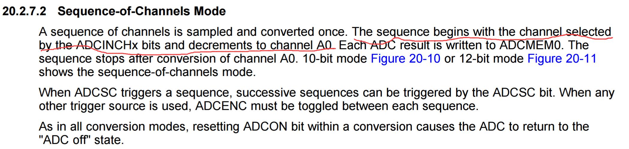
仔细看UG
这个顺序采样有点KD。
选好最高通道,然后依次采到通道0. 不能任意指定通道。。。
您好,我用的A5-A7三个通道,最高置的A7(ADCINCH_7),例程是A0-A2 最高置的A2(ADCINCH_2),这个芯片的序列应该可以是其中的一段序列吧
shuyin qin 说: 您好,我用的A5-A7三个通道,最高置的A7(ADCINCH_7),例程是A0-A2 最高置的A2(ADCINCH_2),这个芯片的序列应该可以是其中的一段序列吧
貌似不可以,你可以试一下 从 A7 到 A0 , 看一下 A7 A6 A5 的值是不是就正常了
A0,A1是串口呀
这段时间刚好在折腾,这个单片机的顺序采样不太好用,只能从你设定的最高通道依次采样到A0,没法跳过低位的通道
jun he3 说: 这段时间刚好在折腾,这个单片机的顺序采样不太好用,只能从你设定的最高通道依次采样到A0,没法跳过低位的通道
是的。