UART有8个串口,UART0调试正常(有范例)但配置在UART1/2/3/4/5/6/7都不能正常通讯,不知道是怎么回事。
怎么调试的?
把你相关代码发上来帮你看看。
不能通讯,你是采用中断还是轮询?
出现的什么错误?
板子是否支持?
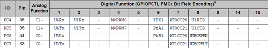
GPIO口有否复用?
//*****************************************************************************
#include "inc/hw_ints.h"
#include "inc/hw_memmap.h"
#include "inc/hw_types.h"
#include "driverlib/debug.h"
#include "driverlib/fpu.h"
#include "driverlib/gpio.h"
#include "driverlib/interrupt.h"
#include "driverlib/sysctl.h"
#include "driverlib/uart.h"
#include "driverlib/rom.h"
#include "grlib/grlib.h"
#include "drivers/cfal96x64x16.h"
//
//! \addtogroup example_list
//! <h1>UART Echo (uart_echo)</h1>
//!
//! This example application utilizes the UART to echo text. The first UART
//! (connected to the USB debug virtual serial port on the evaluation board)
//! will be configured in 115,200 baud, 8-n-1 mode. All characters received on
//! the UART are transmitted back to the UART.
// The error routine that is called if the driver library encounters an error.
#ifdef DEBUG
void
__error__(char *pcFilename, unsigned long ulLine)
{
}
#endif
// The UART interrupt handler.
UARTIntHandler(void)
unsigned long ulStatus;
// Get the interrrupt status.
ulStatus = ROM_UARTIntStatus(UART3_BASE, true);
// Clear the asserted interrupts.
ROM_UARTIntClear(UART3_BASE, ulStatus);
// Loop while there are characters in the receive FIFO.
while(ROM_UARTCharsAvail(UART3_BASE))
// Read the next character from the UART and write it back to the UART.
ROM_UARTCharPutNonBlocking(UART3_BASE,
ROM_UARTCharGetNonBlocking(UART3_BASE));
// Send a string to the UART.
UARTSend(const unsigned char *pucBuffer, unsigned long ulCount)
// Loop while there are more characters to send.
while(ulCount--)
// Write the next character to the UART.
ROM_UARTCharPutNonBlocking(UART3_BASE, *pucBuffer++);
// This example demonstrates how to send a string of data to the UART.
int
main(void)
tRectangle sRect;
tContext sContext;
// The FPU should be enabled because some compilers will use floating-
// point registers, even for non-floating-point code. If the FPU is not
// enabled this will cause a fault. This also ensures that floating-
// point operations could be added to this application and would work
// correctly and use the hardware floating-point unit. Finally, lazy
// stacking is enabled for interrupt handlers. This allows floating-
// point instructions to be used within interrupt handlers, but at the
// expense of extra stack usage.
FPUEnable();
FPULazyStackingEnable();
// Set the clocking to run directly from the crystal.
ROM_SysCtlClockSet(SYSCTL_SYSDIV_1 | SYSCTL_USE_OSC | SYSCTL_OSC_MAIN |
SYSCTL_XTAL_16MHZ);
// Initialize the display driver.
CFAL96x64x16Init();
// Initialize the graphics context.
GrContextInit(&sContext, &g_sCFAL96x64x16);
// Fill the top part of the screen with blue to create the banner.
sRect.sXMin = 0;
sRect.sYMin = 0;
sRect.sXMax = GrContextDpyWidthGet(&sContext) - 1;
sRect.sYMax = 9;
GrContextForegroundSet(&sContext, ClrDarkBlue);
GrRectFill(&sContext, &sRect);
// Change foreground for white text.
GrContextForegroundSet(&sContext, ClrWhite);
// Put the application name in the middle of the banner.
GrContextFontSet(&sContext, g_pFontFixed6x8);
GrStringDrawCentered(&sContext, "OURS-uart3-echo", -1,
GrContextDpyWidthGet(&sContext) / 2, 4, 0);
// Initialize the display and write some instructions.
GrStringDrawCentered(&sContext, "Connect a", -1,
GrContextDpyWidthGet(&sContext) / 2, 20, false);
GrStringDrawCentered(&sContext, "terminal", -1,
GrContextDpyWidthGet(&sContext) / 2, 30, false);
GrStringDrawCentered(&sContext, "to UART3.", -1,
GrContextDpyWidthGet(&sContext) / 2, 40, false);
GrStringDrawCentered(&sContext, "115200,N,8,1", -1,
GrContextDpyWidthGet(&sContext) / 2, 50, false);
// Enable the peripherals used by this example.
ROM_SysCtlPeripheralEnable(SYSCTL_PERIPH_GPIOC);
ROM_SysCtlPeripheralEnable(SYSCTL_PERIPH_UART3);
// Enable processor interrupts.
ROM_IntMasterEnable();
// Set GPIO G4 and G5 as UART pins.
ROM_GPIOPinTypeUART(GPIO_PORTC_BASE, GPIO_PIN_6 | GPIO_PIN_7);
// Configure the UART for 115,200, 8-N-1 operation.
ROM_UARTConfigSetExpClk(UART3_BASE, ROM_SysCtlClockGet(), 115200,
(UART_CONFIG_WLEN_8 | UART_CONFIG_STOP_ONE |
UART_CONFIG_PAR_NONE));
// Enable the UART interrupt.
ROM_IntEnable(INT_UART3);
ROM_UARTIntEnable(UART3_BASE, UART_INT_RX | UART_INT_RT);
// Prompt for text to be entered.
UARTSend((unsigned char *)"Please Enter: ", 16);
// Loop forever echoing data through the UART.
while(1)
能进得了中断吗? 建议你看看寄存器对比下器件手册,看看UART3是否在正常工作
因为UART0的引脚是默认 UART0模式,但是其他的UART单元所使用的引脚需要通过硬件配置下才能使用。可以添加以下两行代码试下:
GPIOPinConfigure(GPIO_PC4_U1RX);
GPIOPinConfigure(GPIO_PC5_U1TX);
PC6和PC7管脚是复用的,所以你需要配置GPIO pin脚的功能
GPIOPinConfigure(GPIO_PC6_U3RX);
GPIOPinConfigure(GPIO_PC7_U3TX);
好的,我试试去,谢谢!
按照您的方法配置了,现在是目标板能发送信号,但接收不了(即:在目标板上复位时,在PC机的串口调试工具里能显示:"please enter:",但PC机端的串口调试工具里点击发送却没有任何反应)
检查一下Startup.c文件中
串口3的中断函数有没有正确注册!怀疑是这个问题!!
或者你在中断函数中设置断点,看看PC上发送文字能否进中断处理函数。
OK,太好了,非常感谢您的支持!
我配置了pin脚还是无法通信,板子reset调试工具什么都无法显示,相同代码配置uart0可以显示。我的代码如下:
int main(void){ char cThisChar; //SysCtlClockSet(SYSCTL_SYSDIV_4|SYSCTL_USE_PLL|SYSCTL_XTAL_16MHZ|SYSCTL_OSC_MAIN); SysCtlClockSet(SYSCTL_SYSDIV_1|SYSCTL_USE_OSC|SYSCTL_OSC_MAIN|SYSCTL_XTAL_16MHZ);
SysCtlPeripheralEnable(SYSCTL_PERIPH_UART1); SysCtlPeripheralEnable(SYSCTL_PERIPH_GPIOB);
GPIOPinConfigure(GPIO_PB0_U1RX); GPIOPinConfigure(GPIO_PB1_U1TX);
GPIOPinTypeUART(GPIO_PORTB_BASE,GPIO_PIN_0|GPIO_PIN_1);
UARTConfigSetExpClk(UART1_BASE,SysCtlClockGet(),115200,(UART_CONFIG_WLEN_8|UART_CONFIG_STOP_ONE|UART_CONFIG_PAR_NONE));
UARTCharPut(UART1_BASE,'!'); do { cThisChar=UARTCharGet(UART1_BASE); UARTCharPut(UART1_BASE,cThisChar);
}while ((cThisChar!='\n')&&(cThisChar!='\r')); return(0);