


各位好:
现遇到如下问题,急切盼望的到解答:
本人采用了库文件里的例程:I2C Master Loopback (i2c_master_slave_loopback)做了部分调整。
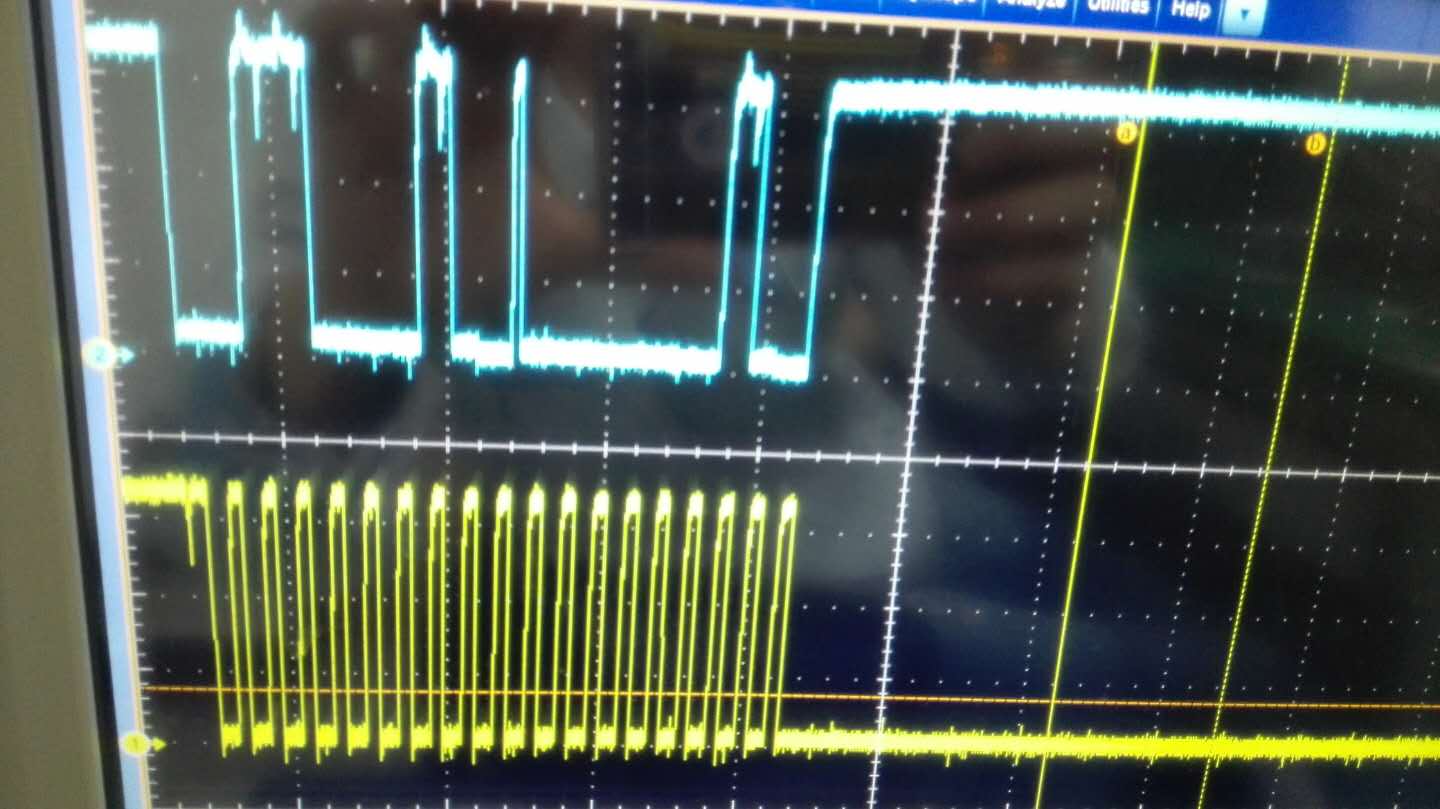
因为要输出到被控对象,因此把loopback功能开启的函数屏蔽了// I2CLoopbackEnable(I2C0_BASE);
但是输出的波形如下,不知道大家有么有遇到这类的问题:
具体的工程如下:
int
main(void)
{
#if defined(TARGET_IS_TM4C129_RA0) || \
defined(TARGET_IS_TM4C129_RA1) || \
defined(TARGET_IS_TM4C129_RA2)
uint32_t ui32SysClock;
#endif
uint8_t pui32DataTx[NUM_I2C_DATA];
uint8_t pui32DataRx[NUM_I2C_DATA];
uint32_t ui32Index;
uint32_t ui32Index1;
main(void)
{
#if defined(TARGET_IS_TM4C129_RA0) || \
defined(TARGET_IS_TM4C129_RA1) || \
defined(TARGET_IS_TM4C129_RA2)
uint32_t ui32SysClock;
#endif
uint8_t pui32DataTx[NUM_I2C_DATA];
uint8_t pui32DataRx[NUM_I2C_DATA];
uint32_t ui32Index;
uint32_t ui32Index1;
//
// Set the clocking to run directly from the external crystal/oscillator.
// TODO: The SYSCTL_XTAL_ value must be changed to match the value of the
// crystal on your board.
//
#if defined(TARGET_IS_TM4C129_RA0) || \
defined(TARGET_IS_TM4C129_RA1) || \
defined(TARGET_IS_TM4C129_RA2)
ui32SysClock = SysCtlClockFreqSet((SYSCTL_XTAL_25MHZ |
SYSCTL_OSC_MAIN |
SYSCTL_USE_OSC), 25000000);
#else
SysCtlClockSet(SYSCTL_SYSDIV_1 | SYSCTL_USE_OSC | SYSCTL_OSC_MAIN |
SYSCTL_XTAL_16MHZ);
#endif
//
// The I2C0 peripheral must be enabled before use.
//
SysCtlPeripheralEnable(SYSCTL_PERIPH_I2C0);
// The I2C0 peripheral must be enabled before use.
//
SysCtlPeripheralEnable(SYSCTL_PERIPH_I2C0);
//
// For this example I2C0 is used with PortB[3:2]. The actual port and
// pins used may be different on your part, consult the data sheet for
// more information. GPIO port B needs to be enabled so these pins can
// be used.
// TODO: change this to whichever GPIO port you are using.
//
SysCtlPeripheralEnable(SYSCTL_PERIPH_GPIOB);
//
// Configure the pin muxing for I2C0 functions on port B2 and B3.
// This step is not necessary if your part does not support pin muxing.
// TODO: change this to select the port/pin you are using.
//
GPIOPinConfigure(GPIO_PB2_I2C0SCL);
GPIOPinConfigure(GPIO_PB3_I2C0SDA);
// Configure the pin muxing for I2C0 functions on port B2 and B3.
// This step is not necessary if your part does not support pin muxing.
// TODO: change this to select the port/pin you are using.
//
GPIOPinConfigure(GPIO_PB2_I2C0SCL);
GPIOPinConfigure(GPIO_PB3_I2C0SDA);
//
// Select the I2C function for these pins. This function will also
// configure the GPIO pins pins for I2C operation, setting them to
// open-drain operation with weak pull-ups. Consult the data sheet
// to see which functions are allocated per pin.
// TODO: change this to select the port/pin you are using.
//
GPIOPinTypeI2CSCL(GPIO_PORTB_BASE, GPIO_PIN_2);
GPIOPinTypeI2C(GPIO_PORTB_BASE, GPIO_PIN_3);
//
// Enable loopback mode. Loopback mode is a built in feature that is
// useful for debugging I2C operations. It internally connects the I2C
// master and slave terminals, which effectively let's you send data as
// a master and receive data as a slave.
// NOTE: For external I2C operation you will need to use external pullups
// that are stronger than the internal pullups. Refer to the datasheet for
// more information.
//
while(1)
{
//
// Enable and initialize the I2C0 master module. Use the system clock for
// the I2C0 module. The last parameter sets the I2C data transfer rate.
// If false the data rate is set to 100kbps and if true the data rate will
// be set to 400kbps. For this example we will use a data rate of 100kbps.
//
#if defined(TARGET_IS_TM4C129_RA0) || \
defined(TARGET_IS_TM4C129_RA1) || \
defined(TARGET_IS_TM4C129_RA2)
I2CMasterInitExpClk(I2C0_BASE, ui32SysClock, false);
#else
I2CMasterInitExpClk(I2C0_BASE, SysCtlClockGet(), false);
#endif
//
// Enable the I2C0 slave module. This module is enabled only for testing
// purposes. It does not need to be enabled for proper operation of the
// I2Cx master module.
//
I2CSlaveEnable(I2C0_BASE);
// Enable the I2C0 slave module. This module is enabled only for testing
// purposes. It does not need to be enabled for proper operation of the
// I2Cx master module.
//
I2CSlaveEnable(I2C0_BASE);
//
// Set the slave address to SLAVE_ADDRESS. In loopback mode, it's an
// arbitrary 7-bit number (set in a macro above) that is sent to the
// I2CMasterSlaveAddrSet function.
//
I2CSlaveInit(I2C0_BASE, SLAVE_ADDRESS);
// Set the slave address to SLAVE_ADDRESS. In loopback mode, it's an
// arbitrary 7-bit number (set in a macro above) that is sent to the
// I2CMasterSlaveAddrSet function.
//
I2CSlaveInit(I2C0_BASE, SLAVE_ADDRESS);
//
// Tell the master module what address it will place on the bus when
// communicating with the slave. Set the address to SLAVE_ADDRESS
// (as set in the slave module). The receive parameter is set to false
// which indicates the I2C Master is initiating a writes to the slave. If
// true, that would indicate that the I2C Master is initiating reads from
// the slave.
//
I2CMasterSlaveAddrSet(I2C0_BASE, SLAVE_ADDRESS, false);
//
// Initalize the data to send.
//
pui32DataTx[0] = 0x02;
pui32DataTx[1] = 0x20;
//
// Place the data to be sent in the data register
//
I2CMasterDataPut(I2C0_BASE, pui32DataTx[0]);
// Place the data to be sent in the data register
//
I2CMasterDataPut(I2C0_BASE, pui32DataTx[0]);
//
// Wait until master module is done transferring.
//
while(I2CMasterBusy(I2C0_BASE))
{
}
// Wait until master module is done transferring.
//
while(I2CMasterBusy(I2C0_BASE))
{
}
I2CMasterControl(I2C0_BASE, I2C_MASTER_CMD_BURST_SEND_START);
while(I2CMasterBusy(I2C0_BASE))
{
}
{
}
ui32Index1 = I2CMasterErr(I2C0_BASE);
while(I2CMasterErr(I2C0_BASE))
{
}
{
}
I2CMasterDataPut(I2C0_BASE, pui32DataTx[1]);
I2CMasterControl(I2C0_BASE, I2C_MASTER_CMD_BURST_SEND_FINISH);
//
// Wait until master module is done transferring.
//
while(I2CMasterBusy(I2C0_BASE))
{
}
// Wait until master module is done transferring.
//
while(I2CMasterBusy(I2C0_BASE))
{
}
I2CSlaveDisable(I2C0_BASE);
}
}


