


SysCtlClockSet(SYSCTL_SYSDIV_4|SYSCTL_USE_PLL|SYSCTL_XTAL_16MHZ|
SYSCTL_OSC_MAIN);
SysCtlPeripheralEnable( SYSCTL_PERIPH_I2C0 );
SysCtlPeripheralEnable( SYSCTL_PERIPH_GPIOB );
//配置相应控制端口
GPIOPinConfigure( GPIO_PB3_I2C0SDA );
GPIOPinConfigure( GPIO_PB2_I2C0SCL );
GPIOPinTypeI2CSCL( GPIO_PORTB_BASE, GPIO_PIN_2 );
GPIOPinTypeI2C( GPIO_PORTB_BASE, GPIO_PIN_3 );
//设置I2C模块传输速率,并使能主机控制功能
I2CMasterInitExpClk( I2C0_BASE, SysCtlClockGet(), false );
I2CMasterEnable( I2C0_BASE );
//
// Enable and configure the GPIO port for the LED operation.
//
SysCtlPeripheralEnable(SYSCTL_PERIPH_GPIOF);
GPIOPinTypeGPIOOutput(GPIO_PORTF_BASE, RED_LED|BLUE_LED|GREEN_LED);
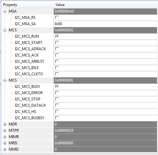
I2CMasterSlaveAddrSet( I2C0_BASE, 0x50, false);
I2CMasterDataPut( I2C0_BASE, 0x00 ); //写入主机数据(寄存器地址)
while( I2CMasterErr(I2C0_BASE) | I2CMasterBusy(I2C0_BASE) );
I2CMasterControl( I2C0_BASE, I2C_MASTER_CMD_BURST_SEND_START ); //主机数据开始传输
while( I2CMasterErr(I2C0_BASE) | I2CMasterBusy(I2C0_BASE) );
I2CMasterDataPut( I2C0_BASE, 0x06 ); //写入主机数据(寄存器内容)
while( I2CMasterErr(I2C0_BASE) | I2CMasterBusy(I2C0_BASE) );
I2CMasterControl( I2C0_BASE, I2C_MASTER_CMD_SINGLE_SEND ); //主机数据+stop传输
while( I2CMasterErr(I2C0_BASE) | I2CMasterBusy(I2C0_BASE) );
I2CMasterSlaveAddrSet( I2C0_BASE, 0x50, false); //????′?ê?·??ò?a?÷?úD′
I2CMasterDataPut( I2C0_BASE, 0x20 ); //D′è??÷?úêy?Y(êy?Y??′??÷μ??·)
while( I2CMasterErr(I2C0_BASE) | I2CMasterBusy(I2C0_BASE) );
I2CMasterControl( I2C0_BASE, I2C_MASTER_CMD_SINGLE_SEND );
while( I2CMasterErr(I2C0_BASE) | I2CMasterBusy(I2C0_BASE) );
//
// Loop Forever
//
while(1)
{
//
// Turn on the LED
//
GPIOPinWrite(GPIO_PORTF_BASE, RED_LED|BLUE_LED|GREEN_LED, RED_LED);
I2CMasterSlaveAddrSet( I2C0_BASE, 0x50, true);
I2CMasterControl( I2C0_BASE, I2C_MASTER_CMD_SINGLE_RECEIVE ); //μ¥′??óê?
while( I2CMasterErr(I2C0_BASE) | I2CMasterBusy(I2C0_BASE) );
Result_H = I2CMasterDataGet( I2C0_BASE );
//
// Delay for a bit
//
SysCtlDelay(2000000);
//
// Turn on the LED
//
GPIOPinWrite(GPIO_PORTF_BASE, RED_LED|BLUE_LED|GREEN_LED, BLUE_LED);
//
// Delay for a bit
//
SysCtlDelay(2000000);
}
可以读其他的,就是不能读写AT24C01,好奇怪
