


Hi,
I used the 3204EVM suite to debug and test AGC. I use the P23 interface in the suite for power supply, use external IC to provide MCLK, WCLK, BCLK, SDA, SCL through I2C change register, MIC input from IN1L, after AGC output from HPL and HPR. Now I have a few questions:
1.I test and find that it has a large white background noise, but PGA Analog Bypass does not have too much white background noise. Is there any way to solve this?
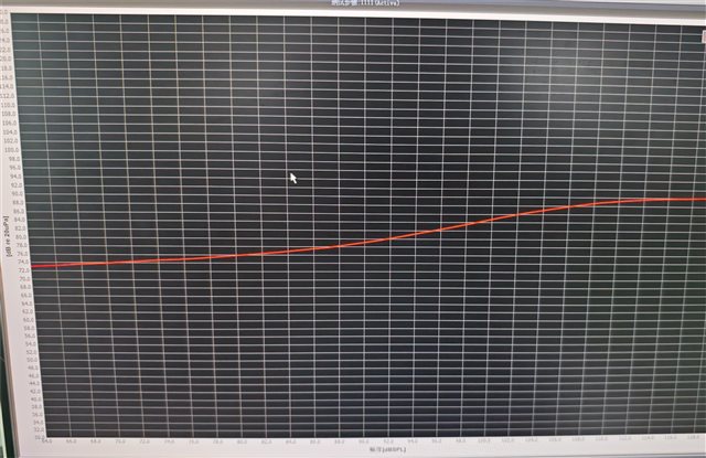
2.Please refer to the compression curve I measured with TLV320. It started with a MIC input of 64 and an output of 74, which is equivalent to a gain of 10 (assuming that the max AGC gain is set to 10). In the middle stage, the maximum AGC gain output should be added if the target level is not reached, but the measured curve does not, and even starts to compress. Is something wrong?Just like the curve below:
Here are the register Settings I used:
###############################################
# Software Reset
###############################################
#
# Select Page 0
w 30 00 00
#
# Initialize the device through software reset
w 30 01 01
#
###############################################

###############################################
# Clock Settings
# ---------------------------------------------
#The input clock signal : MCLK = 11.2896 MHz,BLCK = 1.4 MHz, WCLK = 44.1 kHz
###############################################
#
# Select Page 0
w 30 00 00
#
# NADC = 1, MADC = 2
w 30 12 81 82
#
###############################################

###############################################
AGC
###############################################
w 30 00 00
w 30 57 74
w 30 56 E0
w 30 58 3C
w 30 59 08
w 30 5A 32
w 30 5B 00
w 30 5C 06
###############################################

###############################################
# Enable Loopback Page 0 register 29
###############################################
#
# Loopback enable for stereo audio data
w 30 1D 30
#
###############################################

###############################################
# Signal Processing Settings
###############################################
#
# Select Page 0
w 30 00 00
#
# Set the ADC Mode to PRB_P1
w 30 3d 01
#
###############################################

###############################################
# Initialize Codec
###############################################
#
# Select Page 1
w 30 00 01
#
# Disable weak AVDD in presence of external
# AVDD supply
w 30 01 08
#
# Enable Master Analog Power Control
w 30 02 00
#
# Select ADC PTM_R4
w 30 3d 00
#
# Set the input powerup time to 3.1ms (for ADC)
w 30 47 32
#
# Set the REF charging time to 40ms
w 30 7b 01
#
###############################################

###############################################
# Recording Setup
###############################################
#
# Select Page 1
w 30 00 01
#MICBIAS
w 30 33 50
# Route IN1L to LEFT_P with 10K input impedance
w 30 34 40
#
# Route Common Mode to LEFT_M with impedance of 20K
w 30 36 40
#
# Route IN1R to RIGHT_P with input impedance of 20K
w 30 37 40
#
# Route Common Mode to RIGHT_M with impedance of 20K
w 30 39 40
#
# Unmute Left MICPGA, Gain selection of 6dB to make channel gain 0dB
# Register of 6dB with input impedance of 20K => Channel Gain of 0dB
w 30 3b 0c
#
# Unmute Right MICPGA, Gain selection of 6dB to make channel gain 0dB
# Register of 6dB with input impedance of 20K => Channel Gain of 0dB
w 30 3c 0c
#
# Select Page 0
w 30 00 00
#
# Power up LADC/RADC
w 30 51 c0
#
# Unmute LADC/RADC
w 30 52 00
#
###############################################

###############################################
# High Performance Stereo Playback
# ---------------------------------------------
# PowerTune mode PTM_P3 is used for high
# performance 16-bit audio. For PTM_P4,
# an external audio interface that provides
# 20-bit audio is required.
#
# For normal USB Audio, no hardware change
# is required.
#
# If using an external interface, SW2.4 and
# SW2.5 of the USB-ModEVM must be set to
# HI and clocks can be connected to J14 of
# the USB-ModEVM.
#
# Audio is routed to both headphone and
# line outputs.
###############################################

###############################################
# Clock Settings
# ---------------------------------------------
# The input clock signal : MCLK = 11.2896 MHz,BLCK = 1.4 MHz, WCLK = 44.1 kHz: MCLK = 11.2896 MHz,
###############################################
#
# Select Page 0
w 30 00 00
#
# NDAC = 1, MDAC = 2
w 30 0b 81 82
#
###############################################

###############################################
# Signal Processing Settings
###############################################
#
# Select Page 0
# w 30 00 00
#
# Set the DAC Mode to PRB_P8
w 30 3c 08
#
###############################################

###############################################
# Playback Setup
###############################################
#
# Select Page 1
w 30 00 01
#
# De-pop
w 30 14 25
#
# Route LDAC/RDAC to HPL/HPR
w 30 0c 08 08
#
# Route LDAC/RDAC to LOL/LOR
w 30 0e 08 08
#
# Power up HPL/HPR and LOL/LOR drivers
w 30 09 30
#
# Unmute HPL/HPR driver, 0dB Gain
w 30 10 00 00
#
# Unmute LOL/LOR driver, 0dB Gain
w 30 12 00 00
#
# Select Page 0
w 30 00 00
#
# DAC => 0dB
w 30 41 00 00
#
# Power up LDAC/RDAC
w 30 3f d6
#
# Unmute LDAC/RDAC
w 30 40 00
#
###############################################
