


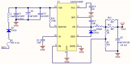
输入电源 57.4V,
输出12.5v,加载后电流195mA
目前测试已烧毁 14PCS,约
13-6 1PCS
13-6-2 5PCS
13-5 1PCS
13-2 3PCS
12-3 5PCS
可否询问一下,这样的设计是否那里有问题呢?谢谢。
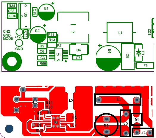
详细图纸见附件
http://www.deyisupport.com/question_answer/analog/power_management/f/24/t/75626.aspx
TI的工程师: Johnsin Tao
直接比对原厂的AN-1352 LM5010 Evaluation Board的测试样板,如同您说的,可能为US1G,
因为整个电路中,就此颗组件配置不同,另外也有看到其它数据,增加R5,使受限的负载可正常输出,
但这个我就没试的,我主要就是一开发,一加载,就烧毁情况均多。
因为没有原厂规格,所以先更换一颗SK220B 200V 2A Surface Mount Schottky Barrier Rectifiers,来测试。
果真,将US1G装上时,就烧毁,换了SK220B,都可正常作动,可能为反向回复电流造成和EMI噪声造成IC烧掉。
但我还是要多测试过。
学习总结:
技术在不断的进步,TI的产品也推陈出新的极快,要时刻保持关注,不断的学习。
目前我们已经使用通过 了解该芯片,还有网友的波形图,感觉此款芯片功能很强大,期待TI的大力支持。